
I am using Autodesk Inventor for a few reasons:
- it is a professional software for engineers and has huge community around it
- it provides free academic license
- there are thousands of youtube videos with detailed tutorials by enthusiasts
- easy to learn at a basic level, but there is always a lot of room for growth
In a lab, there are two main workflows where Inventor is necessary: 3D modeling of complex assemblies (like custom-built microscope) and 3D printing.
There are many youtube tutorials for beginners, so I here only review some things that Inventor can do, without any specific instructions.
3D modeling of parts and assemblies
Before building a new microscope, you can create its virtual model and check dimensions, required adapters, and whether things will fit together. Luckily, Thorlabs has 3D model of nearly all its parts available for free (good job, Thorlabs!). For example, a 100-mm mounted achromat model can be downloaded as STEP file and imported directly into Inventor. It takes a few clicks in the Inventor to add an optical axis and a focal plane of the lens:

Mirrors, lasers, cameras can all be imported as STEP files (if available), or their scale mock-up models can be created in the Inventor.
Autodesk has excellent rendering system, so you can make your parts look as realistic as you wish, by selecting surfaces and their colors (such as Aluminum, Polished).

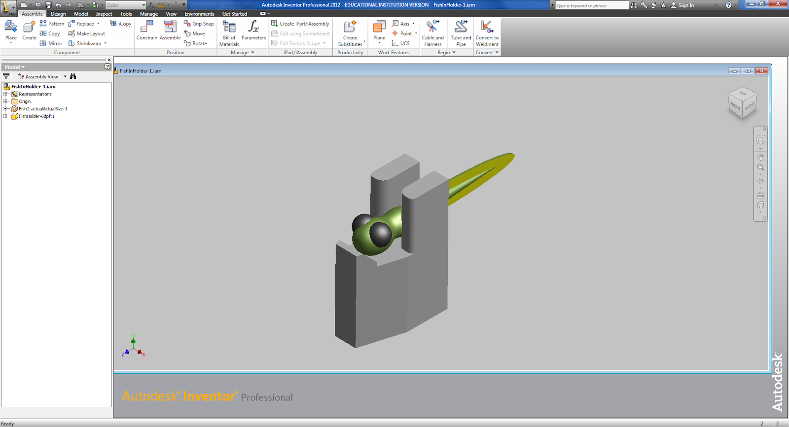
You can make your own 3D models of anything, for example a tiny zebrafish larva in a plastic holder:
Individual parts (including optical table and breadboards) can be combined into assemblies with specified geometrical constrains. A finished microscope project can look like this.

A 3D assembly of system can be a BIG saver of time and money - it's better to know whether you parts fit together before buying them.
3D printing
Making 3D models is a lot of fun, and there are only few basic tools of Inventor you need to start modeling:
- 2D sketch,
- Extrude,
- Revolve,
- Make holes.
For a demo, check how to model a scooter tire in less than 6 min.
Once you created your new shiny 3D model and saved it in .ipt file for posterity (.ipt is Inventor format), re-save it as STL file: Export > CAD Format > STL files (.stl)
The STL is a standard format for 3D models recognized across different software platforms. Open the STL in a software specific for your 3D printer, such as Cura (Makerbot), or PreForm (Formlabs), set the printing parameters and save in printer-specific file format which your printer recognizes. Then print!
Here are some recent examples of stuff I modeled and printed for the lab. The modeling typically required 15-20 min, so it's a no brainer once you know basic steps.
Happy printing!


Hi there, I was looking to visualize my optical setup using Thorlab cad models exactly as you mentioned above. I am really new to CAD designing. Once I download the cad file and open it in the Auto Cad I am really not aware how to proceed. Could you please help me regarding this.
ReplyDeleteMy seemingly silly doubt is how to extrude from the given planar model in thorlabs CAD. Thank You so much:)
Hi there,
DeleteYou need to open the STEP file from Thorlabs in the Inventor, and re-save it as Inventor part (.ipt file). Then, you can combine multiple parts into an assembly, and place them according to spatial constrains you want (eg one surface touching another, optical axes collinear, etc.) Check some Youtube tutorials about assemblies: https://www.youtube.com/watch?v=FqaGonaRBEM
Your opinions are very informative about 3D Modeling Services .Glad you shared all details.
ReplyDeleteThank you very much for posting this blog on 3d modelling services in lab. I found your blog very informative and got to know detailed insights. Are you in need of 3D Modeling Services? They carry out the requirements from the beginning to the end with the utmost expertise and highest quality. One of the most beneficial approaches to achieving the desired outcomes in your architectural design is by using their services.
ReplyDeleteI got to know a lot of detailed insights on 3d modelling services in lab. Thanks for sharing this post. The acorn drawings or CAD 2D and 3D modelling are the latest software that is used in the designing process. It acts as a guiding document for the manufacturers and fabricators with detailed structure drafting. It makes work efficient and allows more quality design by reducing errors, improving accuracy, and productivity and saving money and time.
ReplyDelete